Assembly Manual¤
If you got your Logic as a kit, we provide you with the following step-by-step guide on its assembly. To assemble it, you will need the following:
- a soldering iron
- pliers
- philips screwdriver
- Xacto knife

1. Make sure you have all the material shown in the photo.

2. Insert the buzzer into the board. Make sure that the polarity matches (the
+ smybol on the board matches with the + symbol on the buzzer).

3. Solder the buzzer's leads to the board.

4. Trim the buzzer leads.

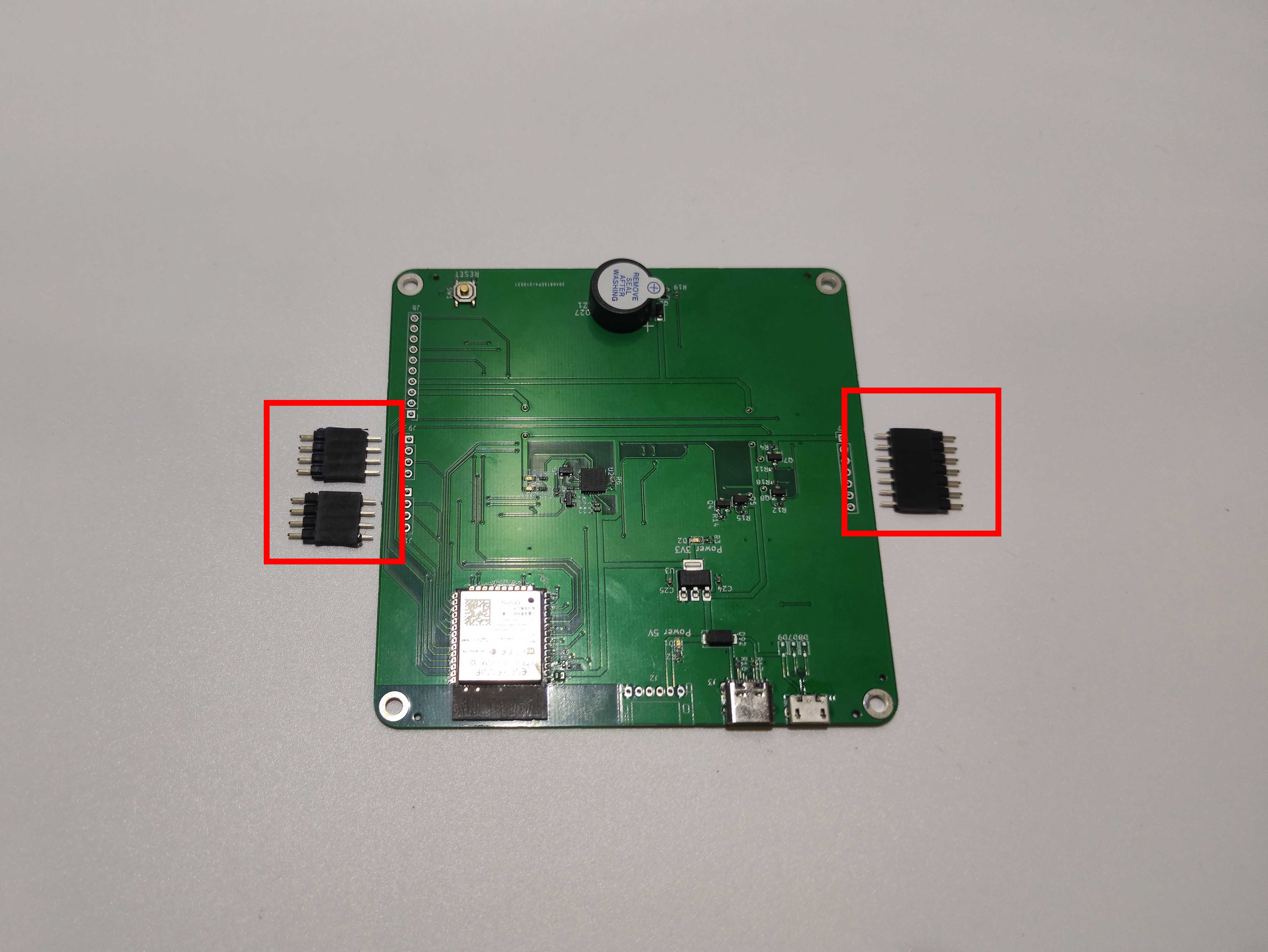
5. Cut pin headers and pin sockets as follows:
- 2× pin headers and sockets with 4 pins
- 1× pin header and a socket with 7 pins

6. Trim any burrs on the headers and sockets using an Xacto knife.

7. Finished headers and sockets.
8. Put pin headers inside the sockets.

9. Put the header inside the corresponding pads in the board.

10. Insert the 4 M3 screws into the board and prepare washers.

11. Insert washers onto the screws.

12. Screw 4 plastic spacers on the screws.

13. Prepare 4 washers.
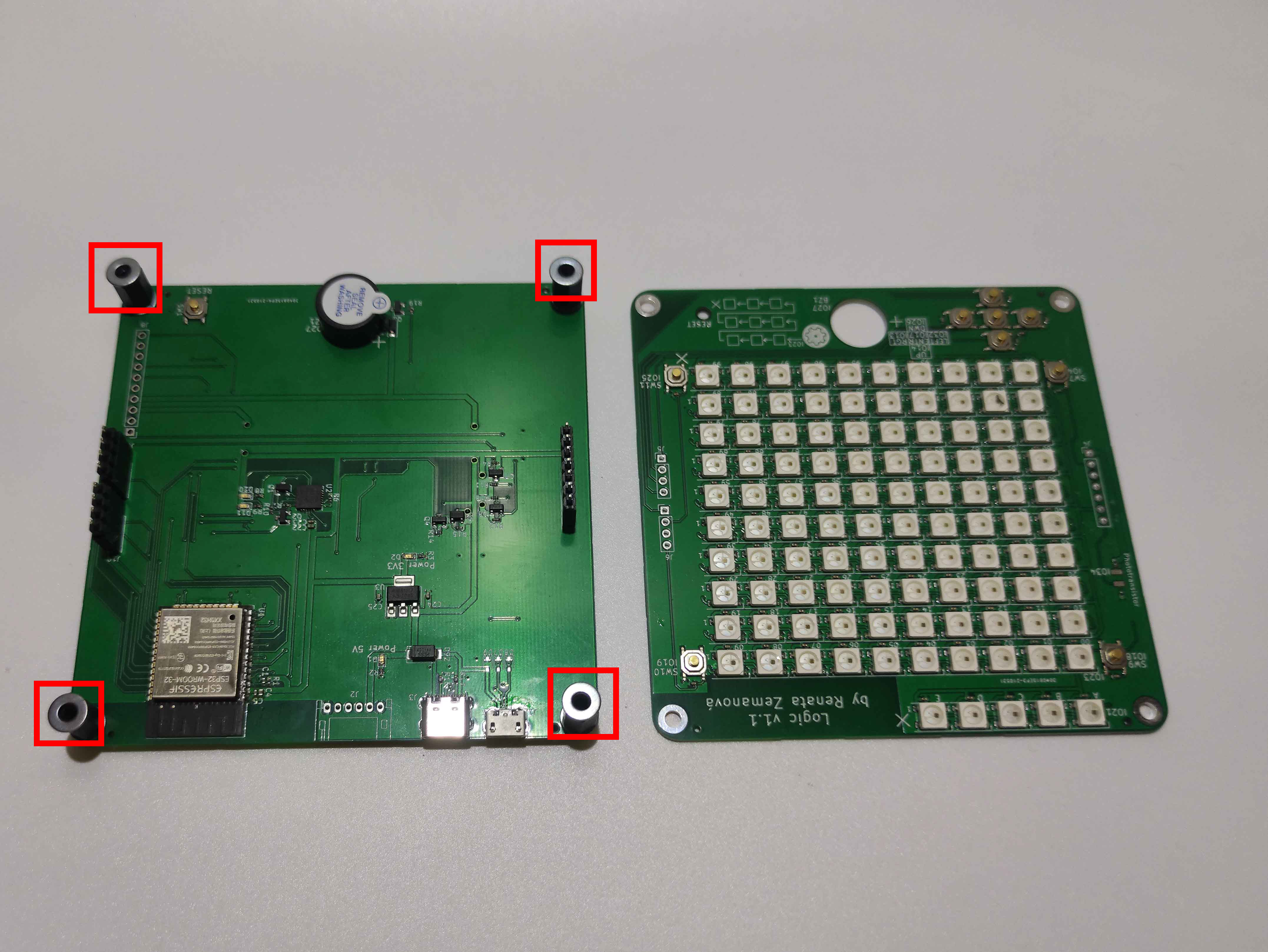
14. Place the washers on the spacers.

15. Put the top board on the assembly.

16. Prepare 4 M3 screws.

17. Tighten the screws.

18. Make sure that the headers are inserted into the top board and the sockets
are inserted in the bottom board.

19. Solder the pin headers.

20. Solder the sockets.

21. Finished Logic – front view.

22. Finished Logic – back view.